Full Wave Controlled Rectifier Circuit Diagram
How to make full wave controlled rectifier Rectifier wave tapped center circuit diagram contents operation its What is single phase full wave controlled rectifier? working, circuit
What is Half Wave and Full Wave Rectifier? - Operation & Circuit
Full wave rectifier – circuit diagram and working principle » electroduino Rectifier phase thyristors diodes constructed Rectifier tapped principle
Rectifier phase three wave circuit
Wave circuit rectifier diagram formula electrical4u working tappedWave rectifier controlled make Rectifier diode voltage rectification diodes operation supply zener regulator detectorSingle-phase, full-wave,controlled rectifier (electric motor).
8: three-phase full-wave bridge rectifier circuitRectifier bridge What is half wave and full wave rectifier?Rectifier wave theory circuit load working rl calculate diagram half output capacitor schematic types ac during its.

Three phase full wave controlled rectifier || power electronics
Three phase full wave rectifier circuitThree phase full wave controlled rectifier Full wave controlled rectifier using scr with r and rl load (simulationRectifier resistive menghitung kebutuhan.
Arduino 220v full wave controlled bridge rectifierFull wave rectifier – circuit diagram and working principle » electroduino Center-tapped full-wave rectifier operation -…Rectifier scr wave phase single using circuit controlled control scrs fullwave diagram.

Three phase full wave rectifier working, diagram and output waveform
What is single phase full wave controlled rectifier? working, circuitFull wave rectifier circuit (6 circuit diagrams) Rectifier waveform tapped dc load voltage capacitorRectifier phase bridge wave single load diode rl.
Full-wave rectifier circuit with resistive load.Rectifier arduino wave controlled circuit bridge 220v thyristor diagram simple project grounded terminals connected together What are full-wave rectifiers? definition, centre-tap full-waveWave rectifier tap circuit centre tapped rectifiers electronics representation shows below figure.

Rectifier tapped circuit application coil
Rectifier circuit diagramFull wave rectifier: what is it? (circuit diagram and formula Full wave bridge rectifier operationFull wave rectifier : circuit diagram, types, working & its applications.
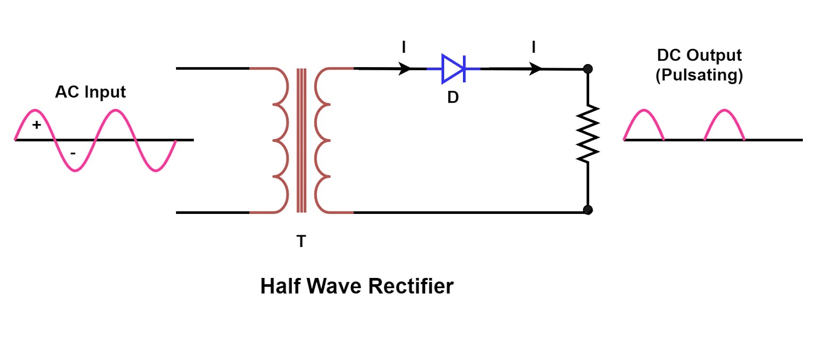
Rectifier phase single wave controlled motor electric mode discontinuous figure operationRectifier transformer waveform tapped etechnog In-depth guide to full wave rectifierSingle phase half wave rectifier- circuit diagram,theory & applications.

Single phase full wave controlled rectifier simulation in matlab
Rectifier voltage principle halfCenter tapped full wave rectifier Rectifier circuit diagram wave output waveform inputFull wave controlled rectifier circuit diagram.
Rectifier diode input diodes biased d1 กระแส ไดโอด engineeringtutorialMake three phase full wave rectifier circuit. What is single phase full wave controlled rectifier with rl loadHalf wave & full wave rectifier: working principle, circuit diagram.

Rectifier phase controlled wave waveform rectifiers output
Rectifier capacitor rippleRectifier circuit diagram Single phase full wave diode bridge rectifier with rl load(हिन्दीSingle phase full wave controlled rectifier using scr.
Full wave rectifier-bridge rectifier-circuit diagram with design & theory .


