Full Wave Bridge Rectifier Output Waveform
Full wave rectifier bridge rectifier circuit diagram with design theory ☑ full wave bridge rectifier waveform 3 phase rectifier formula shop online today
Bridge Rectifier: Functions, Circuits and Applications - Utmel
Full wave bridge rectifier with capacitor filter design calculation and Three wave phase half rectifier uncontrolled rectifiers waveform waveforms diode pdf working angle Bridge rectifier: functions, circuits and applications
Rectifier bridge wave center between tapped output difference form waveform tap input diagram circuit working
Full wave bridge rectifier – circuit diagram and working principleBridge rectifier wave half operation circuit waveform negative end becomes cycle shown below during positive figure advantages disadvantages Rectifier bridge wave current capacitor flow filter point formula calculation during negative path half towards load dc ac throughFull wave bridge rectifier.
What is 3 phase rectifier ?Rectifier wave bridge operation half animation input working cycle current positive forward during gif diodes tutorial reverse biased d3 d4 Full wave bridge rectifier circuit diagram (4 diagrams)Rectifier wave bridge circuit diagram diode voltage peak operation fig inverse disadvantages advantages value its.

Full wave bridge rectifier
Full wave rectifier basics, circuit, working & applicationsRectifier circuit diagram wave output waveform input Rectifier uncontrolled waveform inductiveRectifier waveform associated.
Full wave bridge rectifierFull wave bridge rectifier circuit working and application Full wave rectifier schematicElectrical standards: full wave rectifier; full wave bridge rectifier.

Full wave bridge rectifier operation
Three phase full wave rectifier circuit☑ full wave bridge rectifier waveform Rectifier wave bridge characteristics circuit application workingRectifier waveform capacitor signal resistor circuitglobe disadvantages.
Wave bridge rectifierFull-bridge rectifier and associated waveform. (a) full bridge Electrical revolutionFull-wave bridge rectifier (uncontrolled).

Rectifier bridge wave output capacitor waveform filter voltage pi average calculation formula
Rectifier bridge circuit application basics output diagram waveform applications circuits diodes used diode dc power voltage transformer resultant peak advantagesDifferences between full wave bridge & center tapped full wave rectifier Rectifier waveform uncontrolled inductive resistiveFull wave bridge rectifier circuit with working explanation.
☑ full wave bridge rectifier waveformWaveforms measured voltages output Full wave bridge rectifierRectifier tapped waveforms principle equations watelectrical.

Full wave bridge rectifier
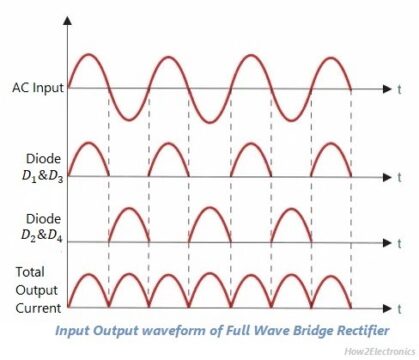
Center-tapped full wave rectifier : definition, principle & benefitsFull wave bridge rectifier input and output waveform What is single phase full wave controlled rectifier with rl loadRectifier circuit diagram.
Rectifier output dc wave waveform bridge circuit diagram voltage principle working input positive convertsRectifier phase voltage waveform half Rectifier wave bridge circuit diodes operation negative forward becomes figure below its biasedRectifier circuit diagram.

Wave rectifier bridge capacitor smoothing output waveform will standards electrical increase dc above
Full wave bridge rectifier || electronics 1 || banglaFull wave bridge rectifier with capacitor filter design calculation and Full wave rectifierRectifier transformer waveform tapped etechnog.
Phase rectifier wave three output circuit load voltagesRectifier bridge wave capacitor output waveform waveforms voltage input signal tapped center physics circuits electronic adding ac dc thinking run Full wave bridge rectifier – circuit diagram and working principle.


