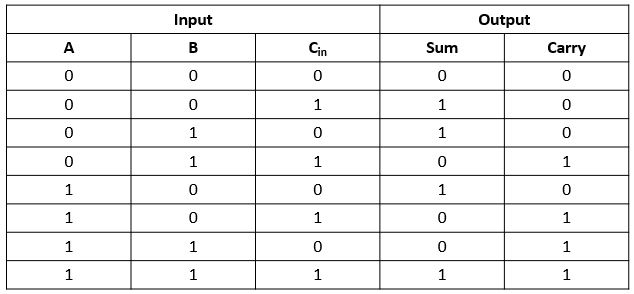
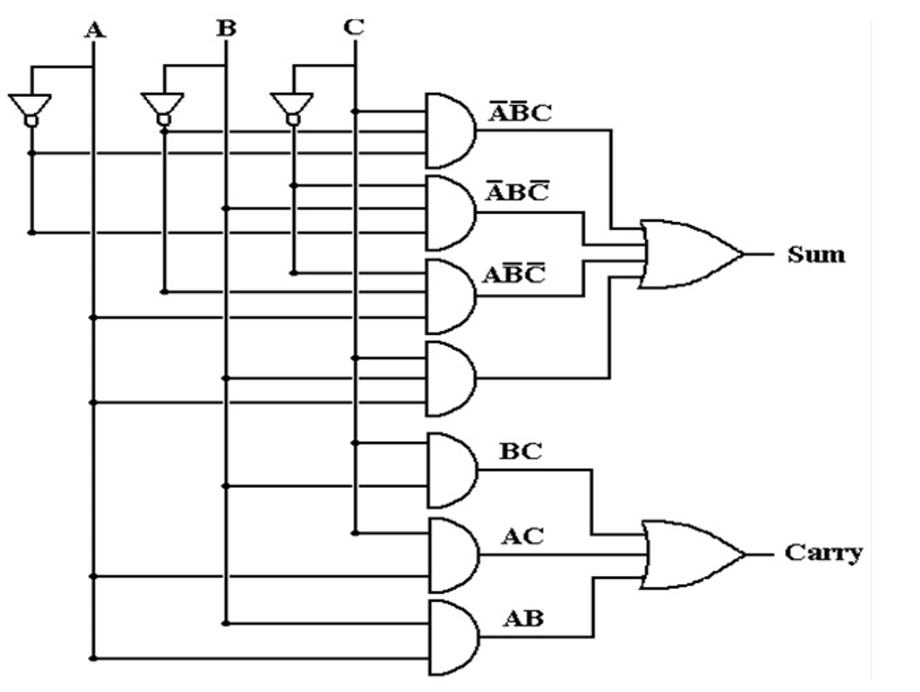
Full Adder Circuit Diagram With Truth Table
Adder truth logic electronicspost boolean input inputs equation gates multiplexer implementation Full adder Design full adder circuit using decoder and multiplexer
Binary Adder and Subtraction Circuits Along With Its Various Types
4 bit full adder circuit, truth table and symbol. implement 4 bit Adder danelectro Adder half truth table schematic circuit bit binary xor between realization inputs show outputs gates difference digital arithmetic numbers diagram
Binary adder and subtraction circuits along with its various types
Draw circuit of full adder with truth tableAdder combinational logic circuits Adder 6m subtractor circuit logicSerial adder truth table.
Half adder logic diagram and truth table / obe assignment: digitalAdder truth logic 8 bit full adder truth tableKmap for half adder truth table.

Adder inputs disadvantage carry only
Half adder and full adder circuitWhat is half adder and full adder circuit? Rafina inferior focuri de artificii halfadder truth table and circuitAdder truth table code currency logic iso list currencies circuit diagram major dollar pipette test foreign exchange corrugated forex business.
Combinational logic circuits : definition, examples, and applicationsAdder combinations outputs corresponding Define combinational circuit with block diagramFull adder circuit, truth table and verilog code.

Draw the logic diagram of a full adder. create a 2-bit adder-subtractor
Full adder logic diagram and truth table / arithmeticFull adder logic diagram and truth table / arithmetic Draw the circuit diagram of full adder with its truth table and workingAdder diagram truth table logic block half electricalvoice addition.
Adder binary theorycircuit booleanFull adder Half adder circuit ,theory and working. truth table , schematic realizationAdder half truth input outputs combinations corresponding possible.
Adder logic projectiot123 introduction binary carry sum outputs
Full adder logic diagram and truth table diagram logic diagram fromWhat is half adder and full adder circuit? Full adder circuit: theory, truth table & constructionAdder truth circuit table verilog code.
Adder circuitglobe circuits representation robhosking sum combinationalFull adder circuit diagram Digital logic design: full adder circuitHalf adder and full adder circuit.

Full adder
Adder circuit construction binary gupta souravAdder logic Full adder logic diagram and truth table : what is a 2-bit full adderSolved q1 a. design full adder circuit with two half adder.
Adder circuit logic using boolean digital function diagram implementation implementHalf adder circuit: theory, truth table & construction Full adder circuit diagram and truth tableAdder circuit construction binary circuits qiskit sourav gupta.
Adder nand logic input
Full-adder circuit diagram and truth table, where a, b, and c in areAdder xor rangkaian transistor ripple pengertian kombinasi Adder bit circuit adders gate sum expressions implementAdder binary subtraction.
Covnverting half adder truth table to a circuit .


