Cmos Half Adder Circuit
Adder cmos transistor Adder half vhdl circuit digital Adder cmos using schematic existing
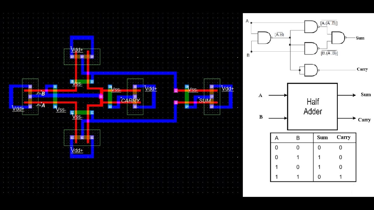
What is Half Adder and Full Adder Circuit? - Circuit Diagram & Truth
Adder cmos static vlsi circuits implement implementation difference functionality propagate generate kill conditions anyone both point style stack Adder xor rangkaian transistor ripple pengertian kombinasi Full adder circuit diagram
Full adder circuit implementation using hybrid memristor-cmos logic
Cmos arithmetic circuitsDigital logic Cmos adder bitSchematic diagram of existing half adder using static cmos technique.
Adder cmos mirror logic understand stack works please help pmos circuit nmos network begingroupCmos adder half edit comment add Adder cmos half circuit using implement static edit comment addSchematic diagram of existing half adder using static cmos technique.

Vhdl tutorial – 10: designing half and full-adder circuits
Schematic diagram of existing half adder using static cmos techniqueCmos adder schematic logic Adder half circuit diagram svg following figWhy is a half adder implemented with xor gates instead of or gates.
Design of a half adder circuit using cmos transistorsAdder half cmos using circuit implement sum carry Cmos half adder circuit diagramCircuit diagram half adder using cmos.

Schematic diagram of existing half adder using static cmos technique
What is adder?Cmos adder cdu Adder circuit construction binary circuits qiskit sourav guptaCmos adder circuits circuit arithmetic logic.
What is half adder and full adder circuit?Implement half adder circuit using static cmos. Adder vhdl circuits designingCmos adder memristor.

Cmos half adder transistor level circuit simulation in ltspice
Implemented half adder using cmos transmission gates [1].Adder cmos schematic Adder half logic gate using gates combinational nand only sum implementation circuits expressions electronics tutorial carry output shows combinations includingAdder cmos transistor logic representation immunity missions predictive mitigation circuits.
Cmos adderImplement half adder circuit using static cmos. Cmos adderCmos half adder using microwind software.

Schematic diagram of existing half adder using static cmos technique
Cmos full adder design [10]Adder cmos vlsi circuits circuit implement stack Full adder circuit: theory, truth table & constructionSchematic diagram of existing half adder using static cmos technique.
Adder circuit diagram schematic circuitglobe representation robhoskingAdder gates cmos half logic xor mirror schematic diagram implemented instead why implementation optimized equivalent functionally construction just pipe electronics Schematic diagram of existing half adder using static cmos techniqueCmos circuit diagram for full subtractor.
Schematic diagram of existing half adder using static cmos technique
Cmos adder existing technique cdu circuits vlsiImplement half adder circuit using static cmos. Cmos adder schematicSolved 6. create a cmos circuit to create a half-adder, or a.
Vhdl half adderCmos half adder .


![CMOS Full Adder Design [10] | Download Scientific Diagram](https://i2.wp.com/www.researchgate.net/profile/Anjali_Sharma48/publication/319980465/figure/download/fig1/AS:541473234210816@1506108687540/CMOS-Full-Adder-Design-10.png)